📦 Getting Started
🔧 Required Hardware
🔌 ESP32 Development Board
The EMS-ESP firmware runs on an ESP32 module from Espressif. The chipsets ESP32 S, S2, S3, C3 ans C6 are supported. Firmware binaries are available for the ESP32 S 4MB, 16MB, 16MB with PSRAM and the ESP32 S3 16MB with PSRAM. For other versions you can build the firmware from the source code using PlatformIO.
See the post here on which development boards we have tested against.
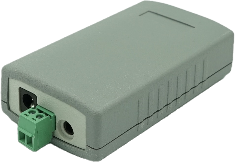
🔗 EMS Interface Board
EMS-ESP also requires a separate circuit to read and write to the EMS bus. You purchase a EMS Gateway board directly from BBQKees Electronics.
💡 LED Status Indicators
When EMS-ESP starts-up and is running, the onboard LED will show the system status.
🔄 During Boot Sequence
1 Flash (blue)
EMS bus is not yet connected. If this takes more than a few seconds check the EMS Tx Mode and the physical connection to the EMS bus.
2 Flashes (red)
Network (WiFi or Ethernet) is connecting. If this persists check the EMS-ESP Network settings. EMS-ESP uses 2.4GHz/WPA2 only.
3 Flashes (red,red,blue)
Both the EMS bus and Network are still trying to connect. This could be due to an incorrect EMS-ESP Board Profile setting.
✨ During Normal Operation
Unless the LED has been disabled in the settings, the LED will show the system status.
Steady Light
Good connection and EMS data is flowing in.
Slow Pulse
Either the WiFi or the EMS bus are still connecting.
Fast Pulse
System is booting up and configuring itself.